It’s late on Friday and we promised to ship the first review firmware this weekend. The firmware isn’t completed yet. However, I’m not working on it either. I just can’t focus. A reviewer is reporting some GPS issues. This person is using a Vector GPS, V1. We only have a V2 of the Vector’s GPS unit to test against noise coming from our 1.2 GHz transmitter, so we find it very hard to duplicate his problems. The reviewer is getting bad HDOP with the V1 GPS receiver around 20-30cm away from our transmitter antenna. The transmitter antenna is mounted higher than the GPS receiver, so that probably doesn’t help.
When you are developing a product transmitting in the 1.2 GHz band, GPS is one of your biggest nightmares. GPS’s signal is -130 dBm, that’s below the noise floor. The thermal noise floor. GPS receivers are marvellous pieces of modern engineering capable of reconstructing a -130 dBm signal on a -110 dBm noise floor using correlation. You don’t want to mess with that.
This post is just some testing on GPS interferences we did this afternoon, and I’m writing about it hoping it can help me clear my mind and move on with the firmware.
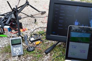
Here are our GPS units:
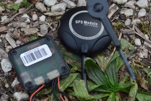 They have nice and big patch antennas and are very directional. The Vector is using smaller antennas, not sure if that’s any less directional.
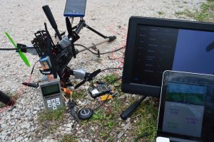
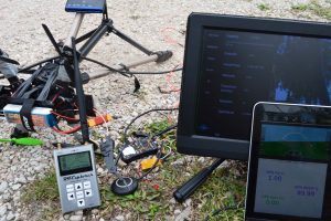
Here is a simple test with the video transmitter turned off: 14 sats, HDOP 0.9.
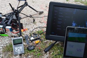
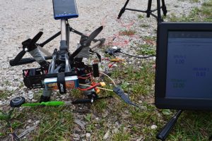 After turning the video transmitter on (max power, as everything else in this post), we couldn’t see any difference. So we moved the GPS antenna right below the body of the transmitter unit. We lost 4 sats, HDOP went up to 1.42.
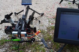 We then pushed a bit further. What happens with the GPS receiver perfectly below the video transmitter antenna? 27 dBm of power are coming out of that antenna, that should kill it. It did kill it.
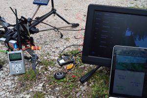
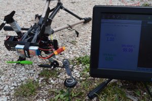 Moving the antenna a bit to the side we got back to 11 sats, HDOP 1.21.
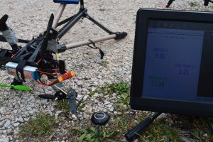 That’s better than expected, after seeing it going to zero. So let’s try to put the transmitter antenna back directly above the GPS unit… Back to zero. There is no need to give you a picture for that. So we flipped the thing around and put the GPS antenna directly on top of the video transmitter. 10 sats. HDOP 1.13. Uhm, better reception is expected, but 10 sats is a bit too good.
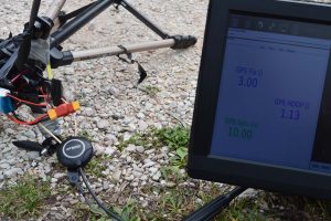 Then something funny happened. I would like to make a wild guess here and claim the GPS module learned how to ignore our RF noise while on top of the transmitter antenna. When we tried putting the transmitter antenna right on top of the GPS receiver, we got 12 sats, HDOP 1.02. Dear GPS receiver, you are a technological miracle. Here is my finger to guesstimate distances.
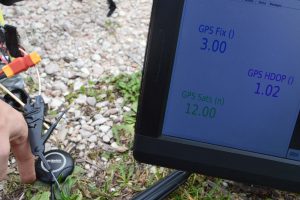 This is where I’m starting to think maybe the transmitter isn’t transmitting anymore, as that’s too good of a result. I will go fetch my portable SA soon and start picturing it as well. Give me a few moments.
Before, we are testing the other GPS unit. Just by guessing from satellite count, this unit is only receiving the actual NAVSTAR’s GPS, not Russian, Chinese or European alternatives. We got 6 sats and HDOP 3.07 with the transmitter turned off. To be fair, that’s a lot of things going around that poor oldi-sh generation GPS receiver. It’s doing great.
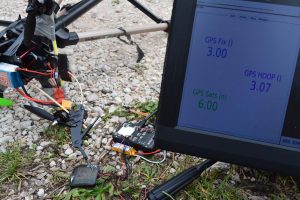 Now let’s power on the video transmitter and see how close to zero satellites I get.
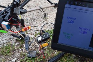 Uhm, this is not good. I gained another satellite and HDOP decreased. And by that I mean it’s too good to be true. The transmitter must be broken. First time a transmitter breaks just like that, but there is no other possible solution. Depression starts to kick in and I go fetch my portable SA I was talking about before. Certainly something broke.
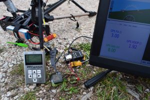 Uhm… No. There is a lot of power coming out of that antenna, and the GPS is acting like a honey badger. Let me link that video to improve morale (my morale).
Here is a technical explanation. The older GPS unit has a very narrow bandpass filter at 1575 MHz. The other GPS unit didn’t, as it needed to accept a wider range of frequencies to catch those Russian satellites as well. I won’t say this is the correct explanation, but that’s what I gave myself when I realised the transmitter was still sending out all that power. Let’s move on.
Surely, I thought, that means there is noise coming out of that antenna and just so it happens it’s not hitting the narrow band of the first L1 transmissions. So, naturally, changing frequencies must destroy performances. Let’s try to run some tests at different frequencies…
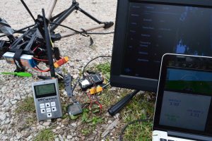
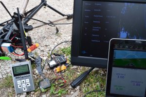
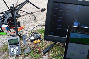
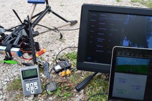
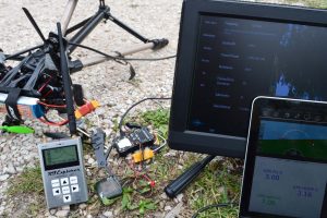
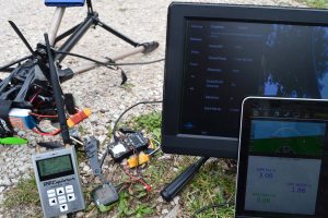
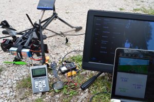 Nothing. The honey badger doesn’t care. 500mW of power at 7 different frequencies and it’s still working. Fine, let’s go back to the old GPS receiver, see if we can destroy that guy’s performances.
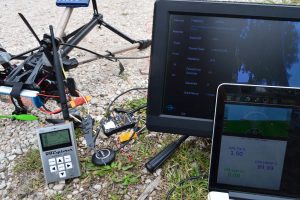 Sure enough, that thing is dead. Let’s try to change frequency.
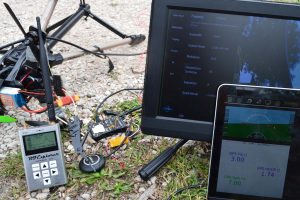 Still pretty bad, but much better. I then tried to go down in frequency in 5 MHz intervals until I got too bored. Nothing very interesting happened, as you can expect some frequencies are working better than others.
Most of the frequencies are killing the GPS receiver. Here is with the transmitter disconnected:
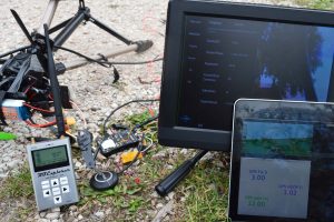 And here is with the transmitter not perfectly above the GPS receiver, as you can see performances are improving dramatically:
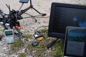
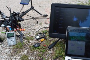
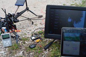
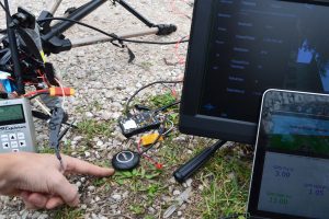 The finger is again to get very accurate distance measurements. By this time I’m getting tired. Let’s try to see what happens with the antenna on the same plane as the GPS unit, a few centimetres away.
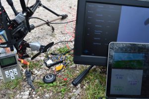 Perfect reception. We need to get closer.
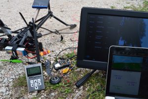
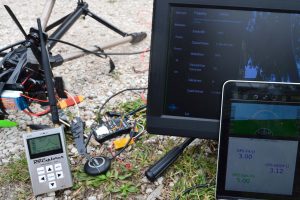
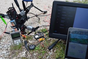 A few sats lost. That’s more like it. Here comes the last batch of images, another frequency run at this distance.
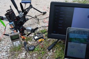
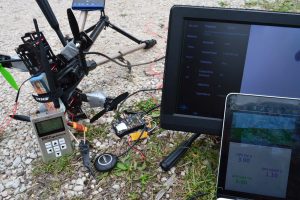
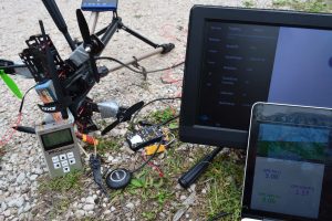
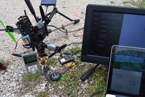
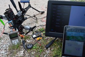
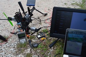
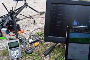
 And it’s with an antenna 0-cm away, 12 sats and a 0.99 HDOP that we conclude this blog post.
Takeaways
This transmitter works in the 1240-1300 MHz band. Some GPS frequencies are just below, others are just above it. It’s the first version of our transmitter and RF filtering isn’t as good as we would like it to be. Filtering ~250 MHz away is hard, not to say impossible.
In the meanwhile, here are our suggestions:
- Fly with a recent GPS unit. The Ublox M8N was, in our opinion, performing great. If you have a Vector GPS V1, please upgrade to V2. Our V2 results were pretty good (and again, we couldn’t test V1).
- Try mounting the transmitting antenna lower than the GPS receiver. The GPS receiver’s patch should be pointing at the sky with its RF aperture unobstructed. If you can’t mount the GPS higher, try to mount it at least on the same plane, don’t mount the video transmitting unit higher.
- Test what your results are for the frequencies you want to use. Those new generation GPS receivers take just a few seconds to lock in a lot of satellites, there is no reason not to test them for the frequency you selected before your flight.
- It might not be a good idea to use an old GPS unit mounted close to the transmitter/antenna.
- Don’t fly if you are not happy with your HDOP. Send us an email instead.
That was a long post. Now let’s see if I can mange to finish this firmware on time.

Hi Davide, What’s the proper way to mount the Tx antenna on a fixed wing plane?Should i mount it vertically (i mean antenna holder arm pointing up to the sky at 90 degrees)? Or i should lay it flat?Will laying it flat decrease its performance?(If i lay it flat and mount the gps at the same level?Could you please provide picture of properly mounted antenna on a fixed wing?It will help a non RF expert like me:) Thanks.
Hi Gary, we already talked in private but here is the answer again for future readers: the antenna should be pointing to the sky. If you want to have a flat antenna you should make sure its longest side is perpendicular to the front-back axis of the plane. You will then have the poorest signal when the wings of the plane are facing you. You should watch this video to never have a question about antenna polarisation again: https://vimeo.com/8826952