Please take a few seconds to read the kind of emails you can get when subscribed to our RCGroups thread:
—Quote (Originally by fpv.blue)—
Just wanted to point out that there is no advantage in using circular polarisation with this system, so you probably shouldn’t as the antennas are so expensive.
—End Quote—
Well that is pretty concerning, I hope your answer is a translation issue and not you understanding of RF.
Of course circular polarisation can and probably will help this system in most environments (that is not a straight open field with no obstacles ), I don’t believe you have managed to change the laws of physics with this device…….
Dear poster whose name I removed, let me explain how we managed to change the laws of physics. Or rather, how we are working around them.
In OFDM, the beginning of each symbol is preceded by a guard interval. As long as the echoes fall within this interval, they will not affect the receiver’s ability to safely decode the actual data, as data is only interpreted outside the guard interval.
Circular polarisation is popular with analog FPV because of its ability to attenuate reflected signal propagation paths by a few decibels. You don’t want reflected paths in analog FPV as they will be interpreted by the analog receiver at the same time as the actual, non reflected RF signal, reducing the performances of the latter.
However, fpv.blue, being a digital system, can completely reject reflected paths. We have a nice guard interval option in our modulation menu, where you can select the length of this guard interval. If you are flying to another galaxy you might want to use 1/4 as a guard interval (one quarter of the symbol length will not be interpreted and the receiver will sleep waiting for echoes to go away).
1/4 can reject reflected paths up to 64 kilometres away (see the menu for more details). We really should be removing this option as the free space path loss for 64 kilometres is huge anyway and people might be selecting it, decreasing video bandwidth for no reason. A more reasonable value is 1/16, that is selected by default.
Antennas
If you already have expensive circularly polarized antennas that are in good condition, use them! If someone told you you need to purchase expensive antennas to have good performances with this system, link them this blog post.
If you really feel crazy about range, you can get a yagi… That you will probably want to use beside a patch as manually pointing yagis is notoriously difficult, so just stick to the patch.
It’s late on Friday and we promised to ship the first review firmware this weekend. The firmware isn’t completed yet. However, I’m not working on it either. I just can’t focus. A reviewer is reporting some GPS issues. This person is using a Vector GPS, V1. We only have a V2 of the Vector’s GPS unit to test against noise coming from our 1.2 GHz transmitter, so we find it very hard to duplicate his problems. The reviewer is getting bad HDOP with the V1 GPS receiver around 20-30cm away from our transmitter antenna. The transmitter antenna is mounted higher than the GPS receiver, so that probably doesn’t help.
When you are developing a product transmitting in the 1.2 GHz band, GPS is one of your biggest nightmares. GPS’s signal is -130 dBm, that’s below the noise floor. The thermal noise floor. GPS receivers are marvellous pieces of modern engineering capable of reconstructing a -130 dBm signal on a -110 dBm noise floor using correlation. You don’t want to mess with that.
This post is just some testing on GPS interferences we did this afternoon, and I’m writing about it hoping it can help me clear my mind and move on with the firmware.
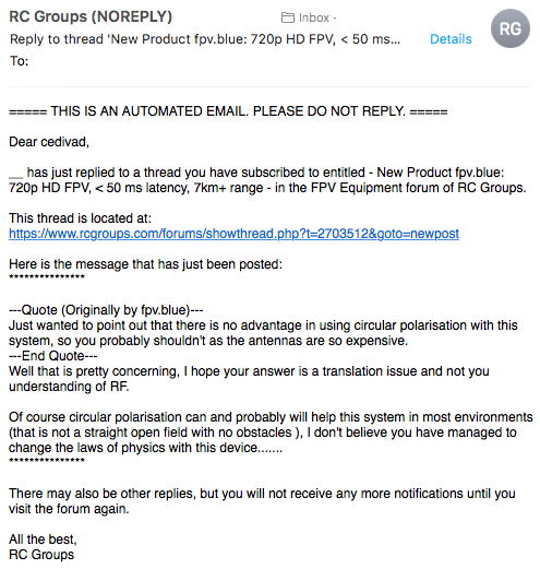
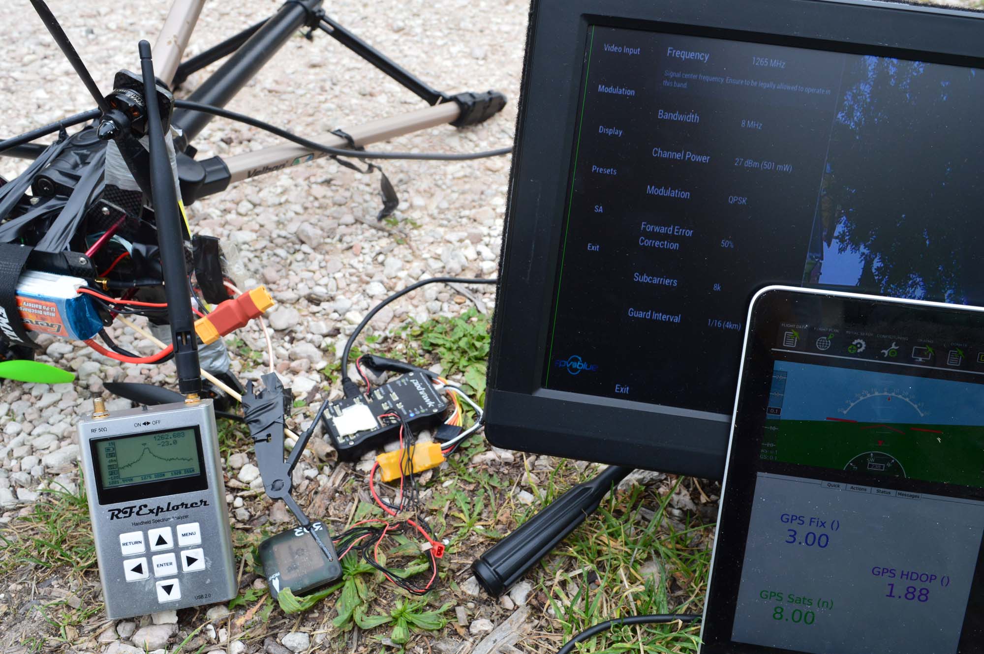
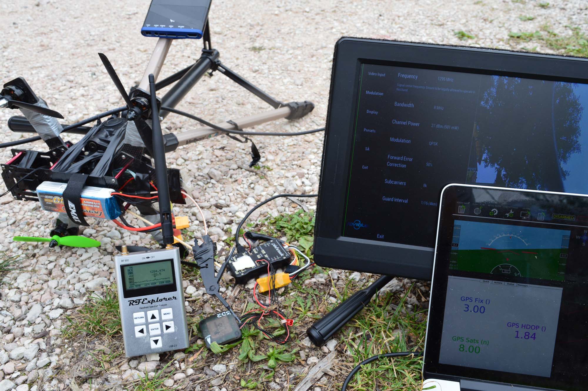
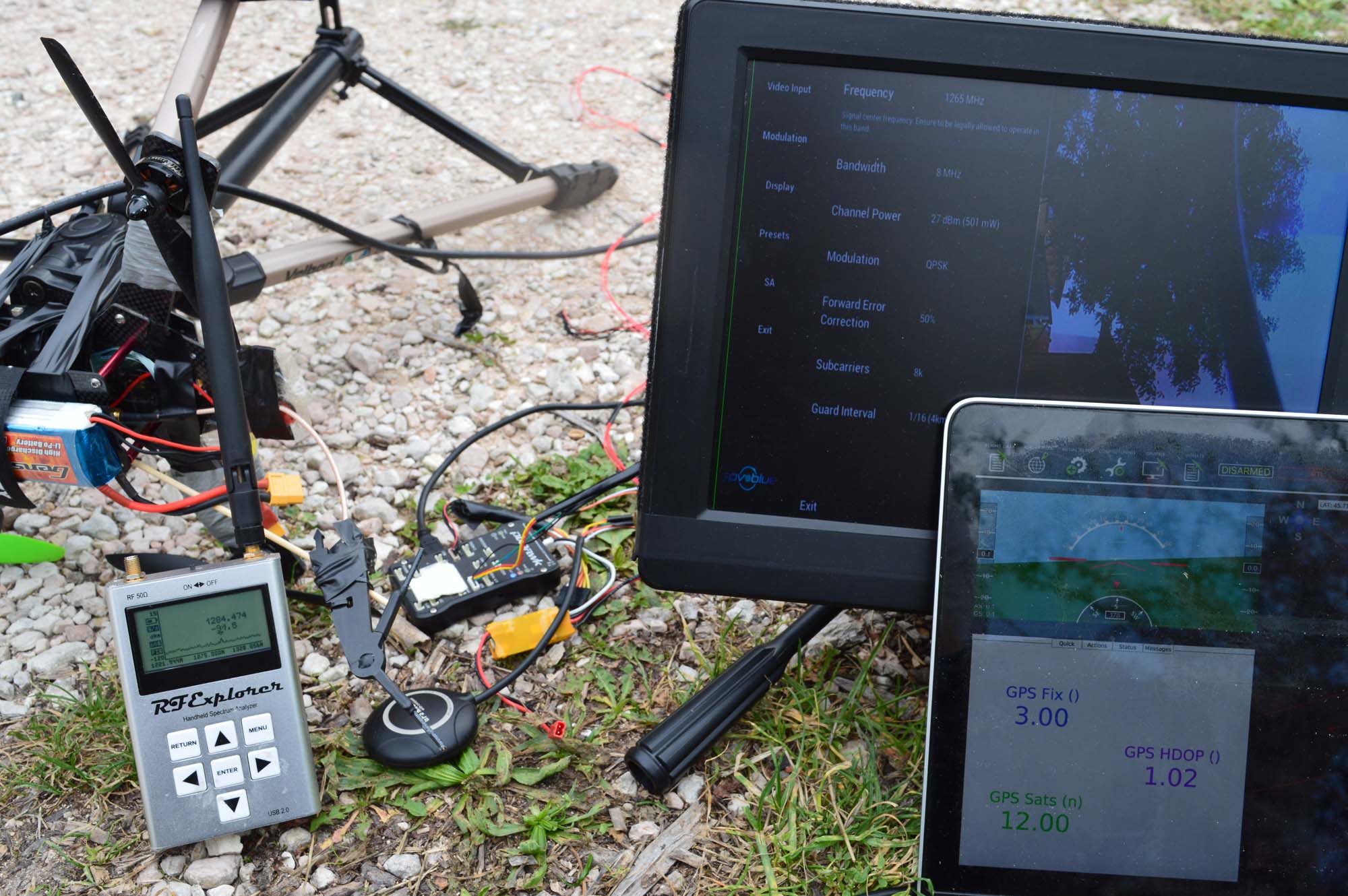
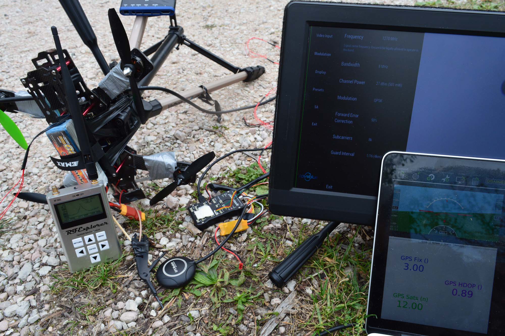
Here are our GPS units:
They have nice and big patch antennas and are very directional. The Vector is using smaller antennas, not sure if that’s any less directional.
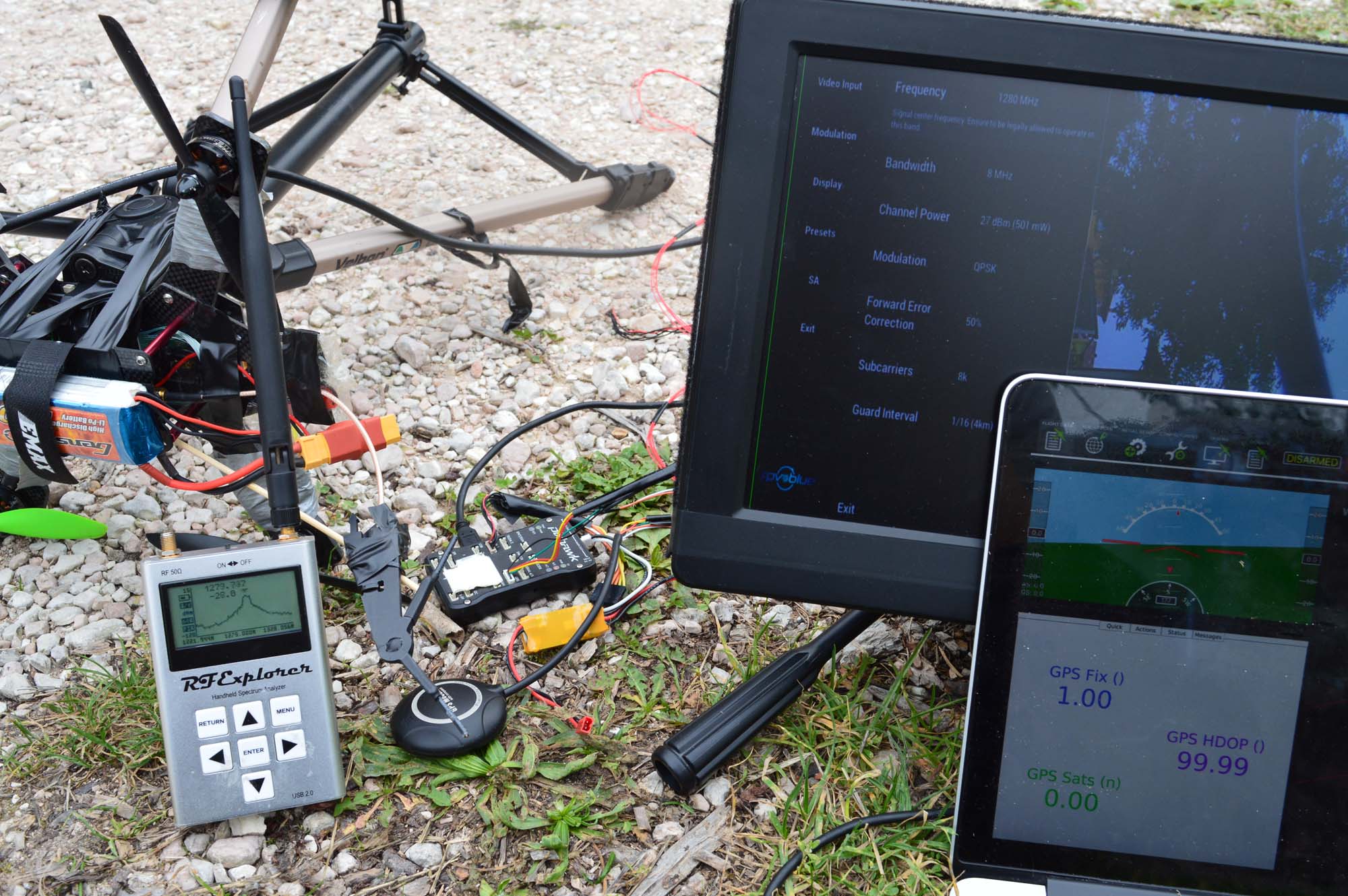
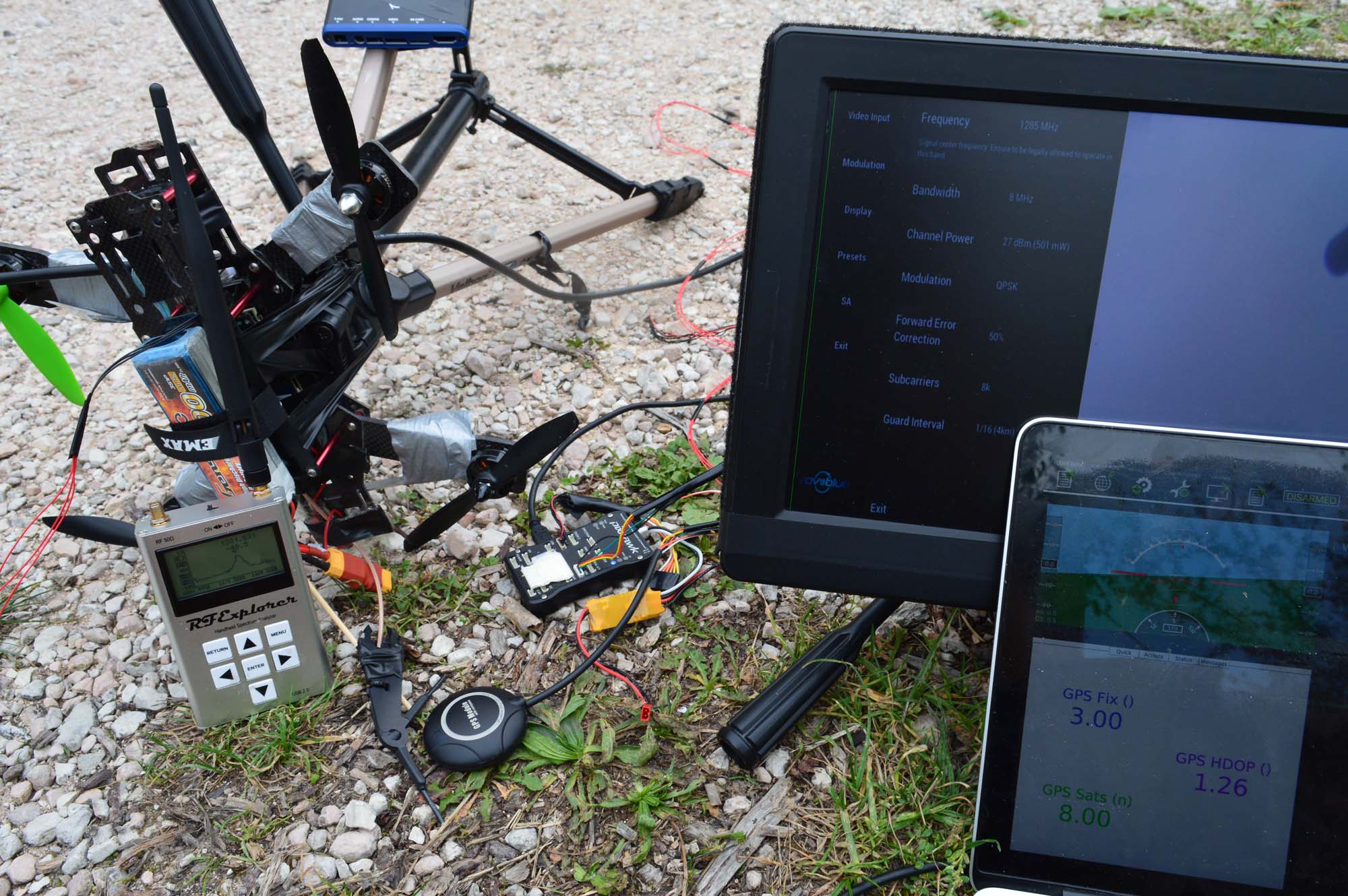
Here is a simple test with the video transmitter turned off: 14 sats, HDOP 0.9.
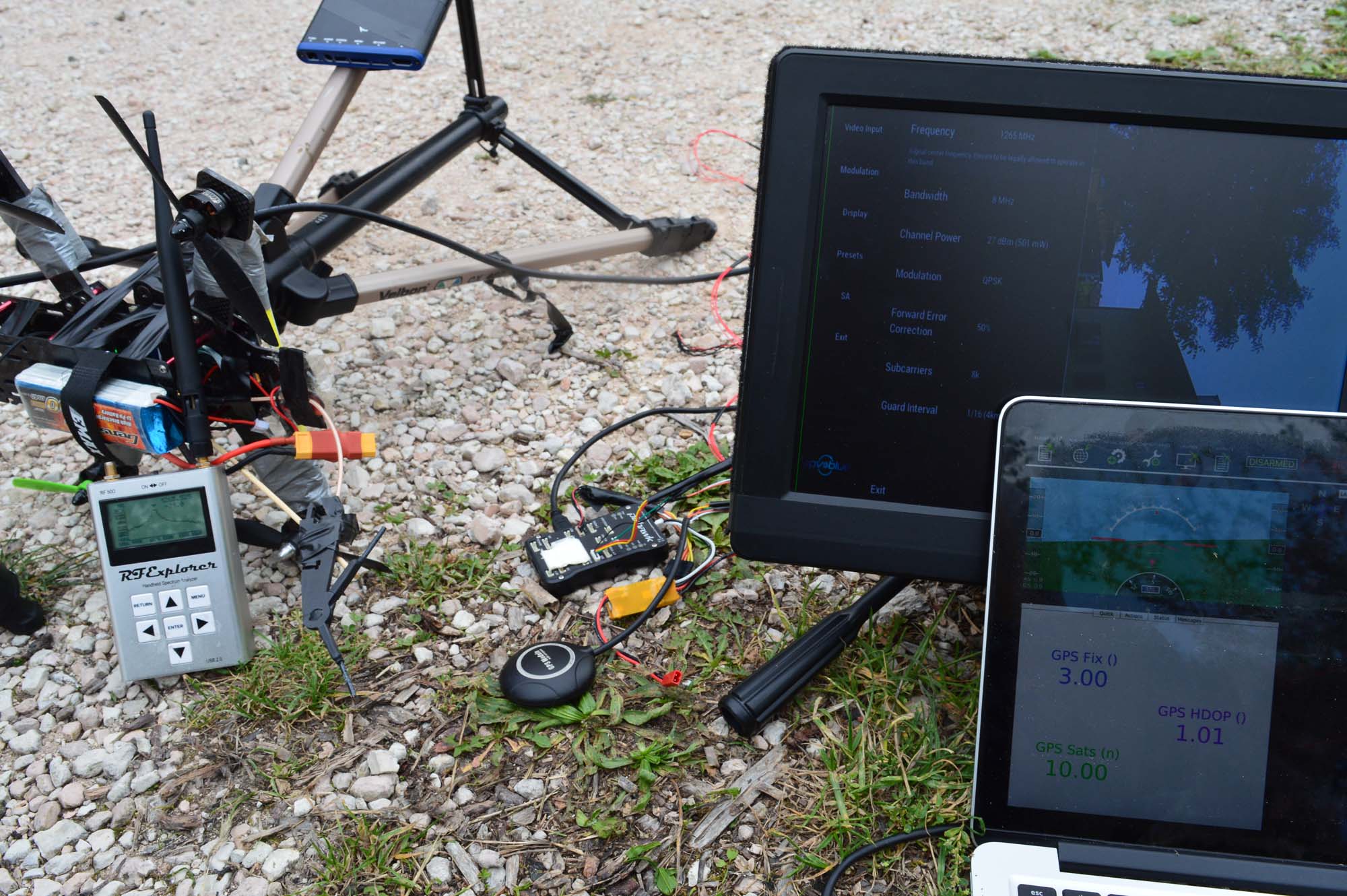
After turning the video transmitter on (max power, as everything else in this post), we couldn’t see any difference. So we moved the GPS antenna right below the body of the transmitter unit. We lost 4 sats, HDOP went up to 1.42.
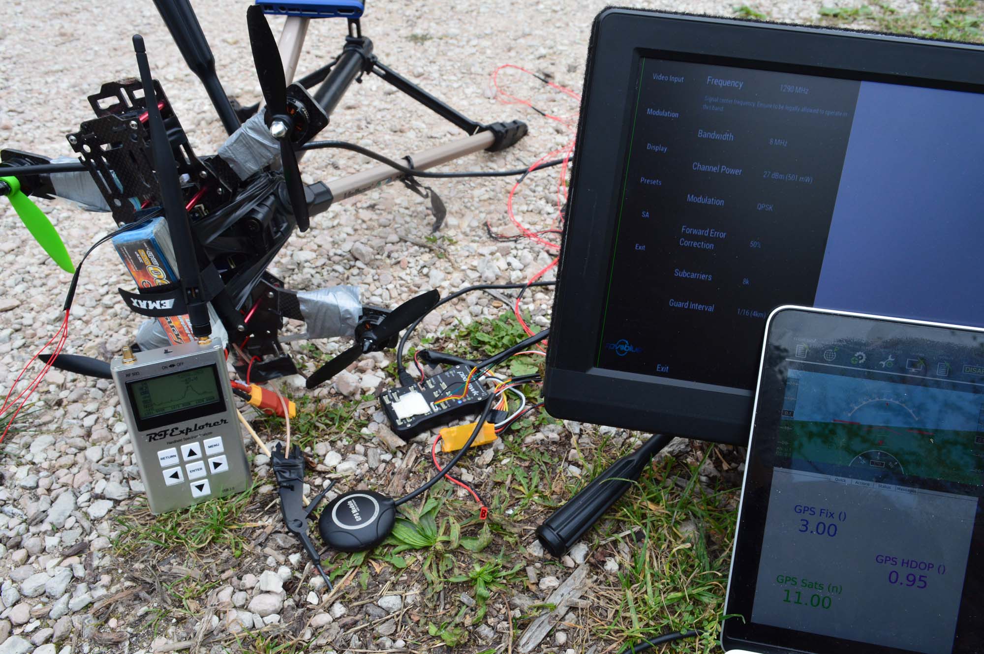
We then pushed a bit further. What happens with the GPS receiver perfectly below the video transmitter antenna? 27 dBm of power are coming out of that antenna, that should kill it. It did kill it.
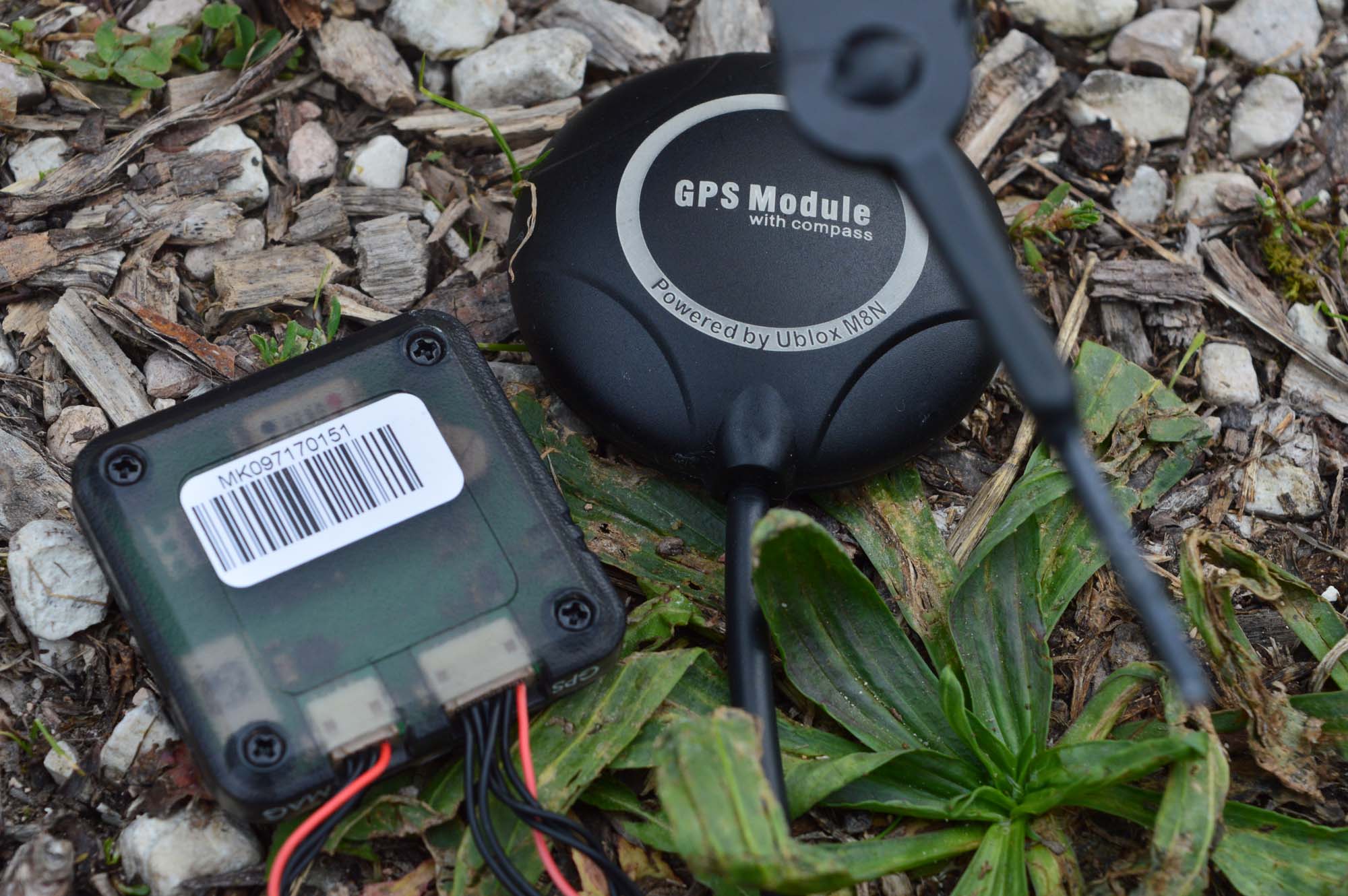
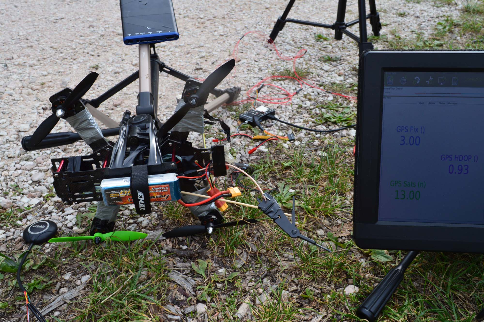
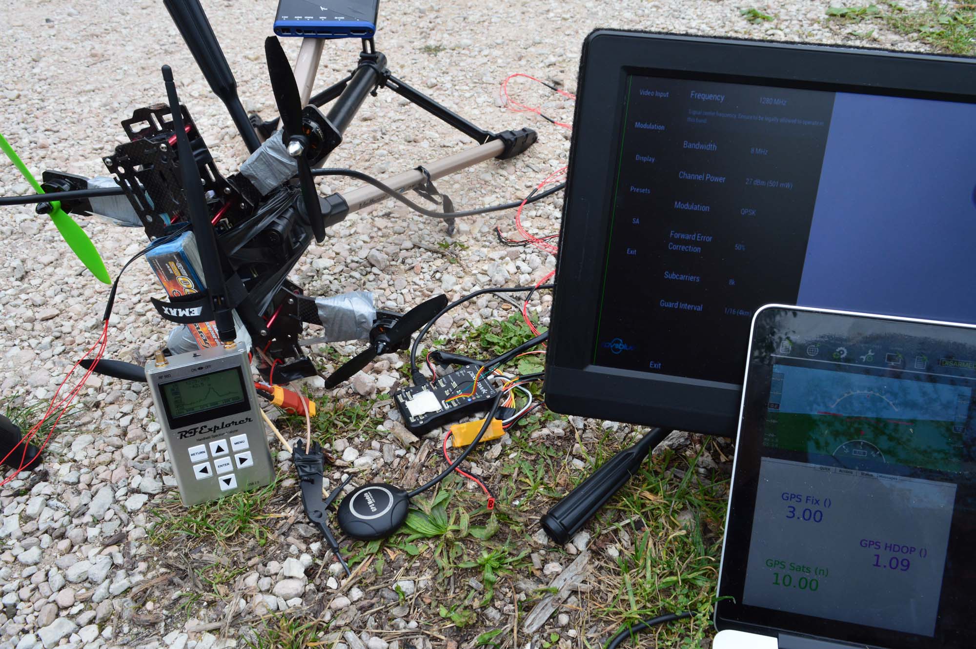
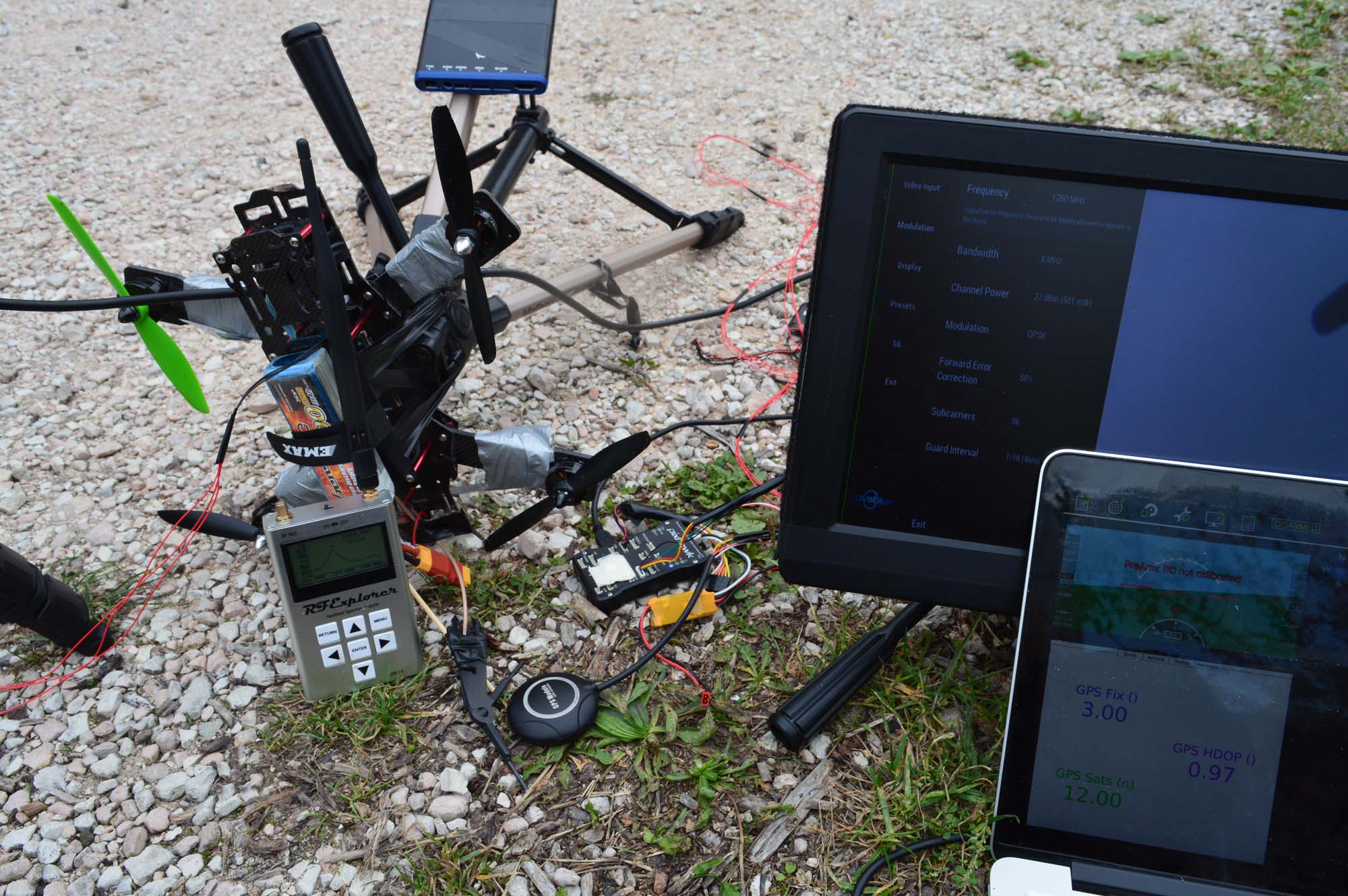
Moving the antenna a bit to the side we got back to 11 sats, HDOP 1.21.
That’s better than expected, after seeing it going to zero. So let’s try to put the transmitter antenna back directly above the GPS unit… Back to zero. There is no need to give you a picture for that. So we flipped the thing around and put the GPS antenna directly on top of the video transmitter. 10 sats. HDOP 1.13. Uhm, better reception is expected, but 10 sats is a bit too good.
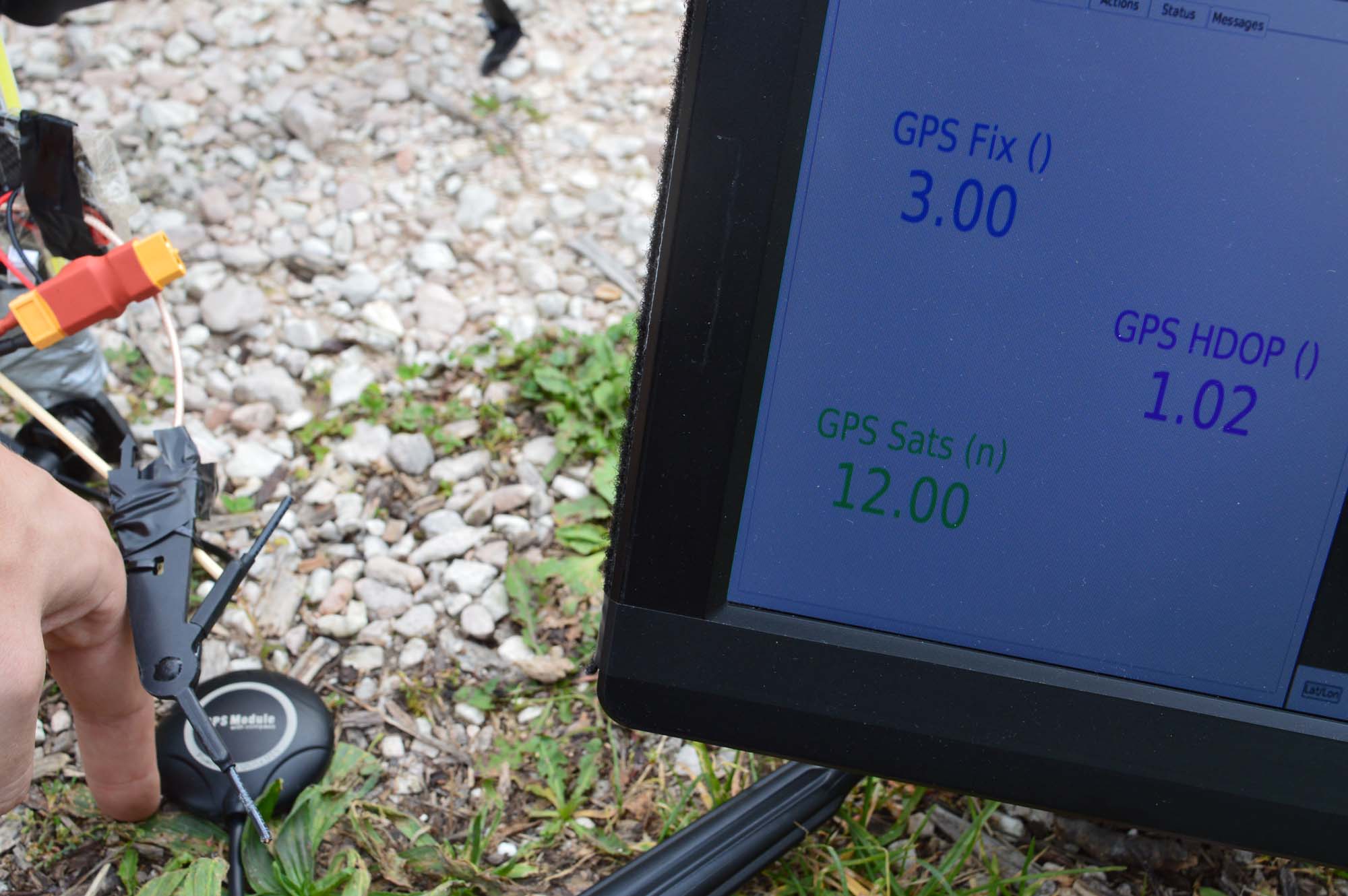
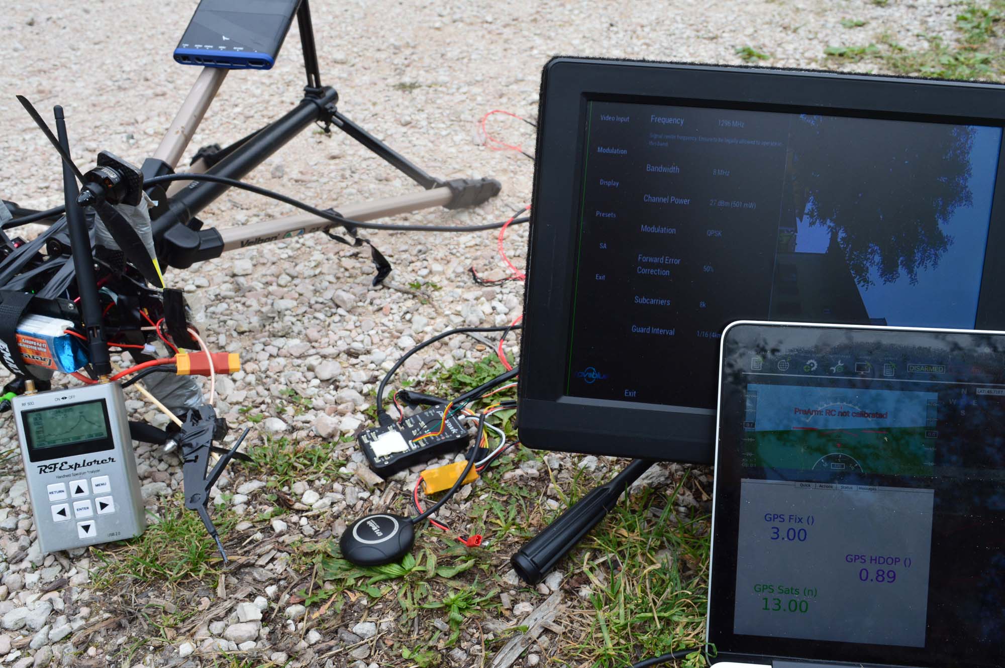
Then something funny happened. I would like to make a wild guess here and claim the GPS module learned how to ignore our RF noise while on top of the transmitter antenna. When we tried putting the transmitter antenna right on top of the GPS receiver, we got 12 sats, HDOP 1.02. Dear GPS receiver, you are a technological miracle. Here is my finger to guesstimate distances.
This is where I’m starting to think maybe the transmitter isn’t transmitting anymore, as that’s too good of a result. I will go fetch my portable SA soon and start picturing it as well. Give me a few moments.
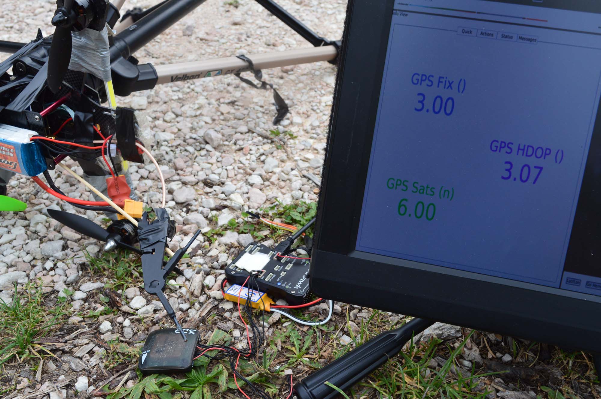
Before, we are testing the other GPS unit. Just by guessing from satellite count, this unit is only receiving the actual NAVSTAR’s GPS, not Russian, Chinese or European alternatives. We got 6 sats and HDOP 3.07 with the transmitter turned off. To be fair, that’s a lot of things going around that poor oldi-sh generation GPS receiver. It’s doing great.
Now let’s power on the video transmitter and see how close to zero satellites I get.
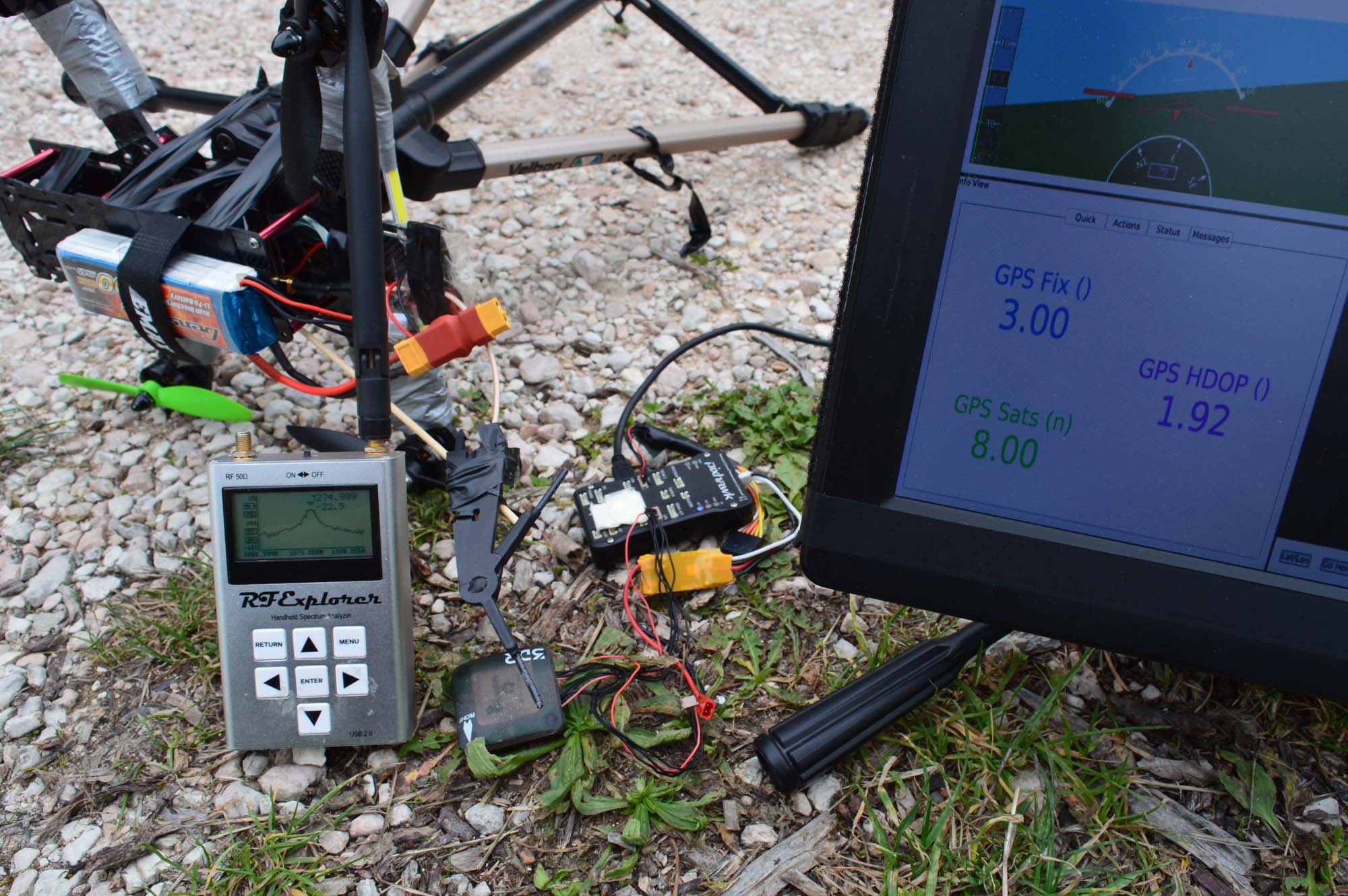
Uhm, this is not good. I gained another satellite and HDOP decreased. And by that I mean it’s too good to be true. The transmitter must be broken. First time a transmitter breaks just like that, but there is no other possible solution. Depression starts to kick in and I go fetch my portable SA I was talking about before. Certainly something broke.
Uhm… No. There is a lot of power coming out of that antenna, and the GPS is acting like a honey badger. Let me link that video to improve morale (my morale).
Here is a technical explanation. The older GPS unit has a very narrow bandpass filter at 1575 MHz. The other GPS unit didn’t, as it needed to accept a wider range of frequencies to catch those Russian satellites as well. I won’t say this is the correct explanation, but that’s what I gave myself when I realised the transmitter was still sending out all that power. Let’s move on.
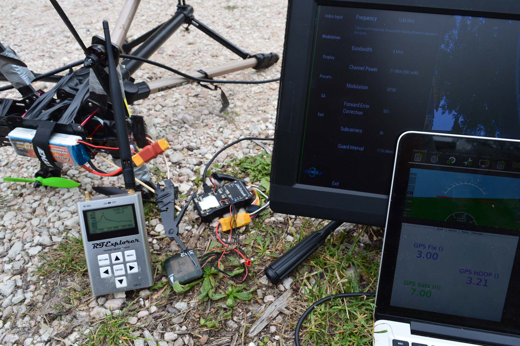
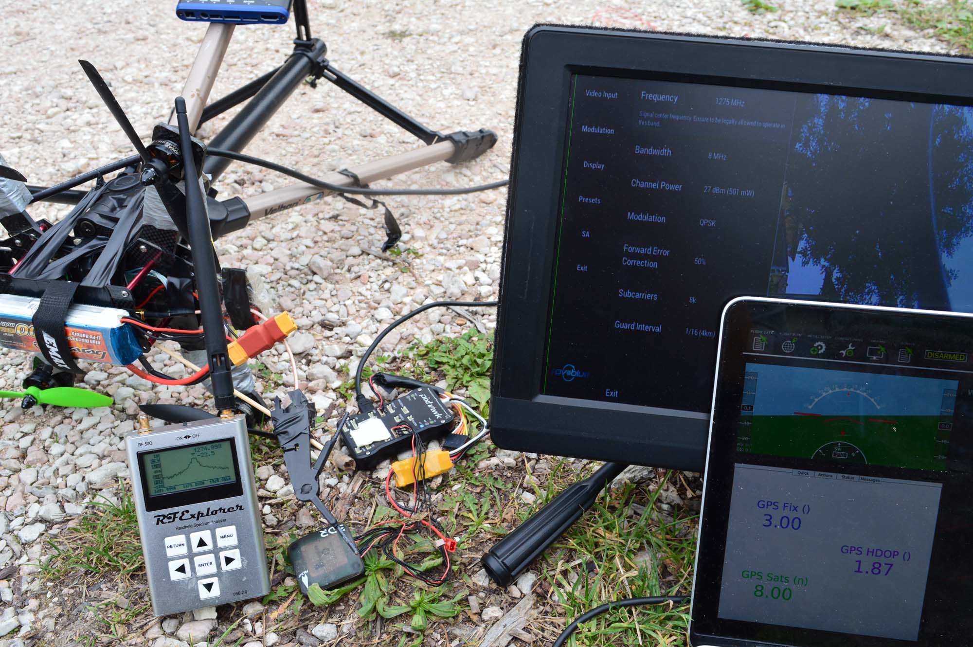
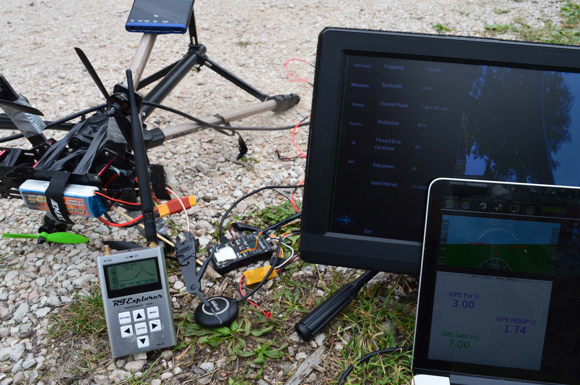
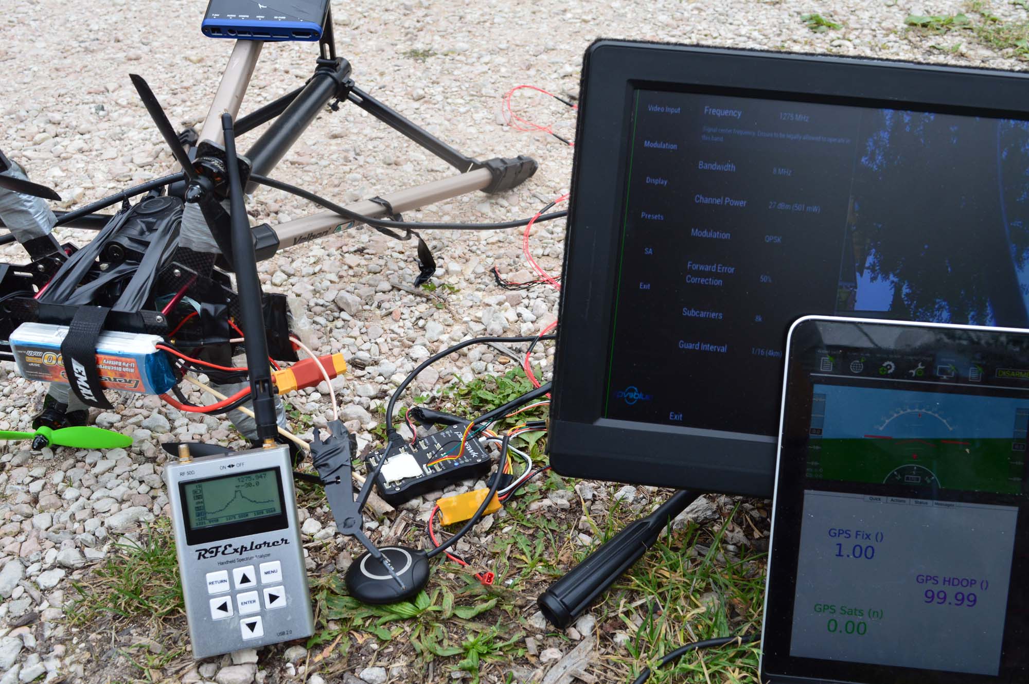
Surely, I thought, that means there is noise coming out of that antenna and just so it happens it’s not hitting the narrow band of the first L1 transmissions. So, naturally, changing frequencies must destroy performances. Let’s try to run some tests at different frequencies…
Nothing. The honey badger doesn’t care. 500mW of power at 7 different frequencies and it’s still working. Fine, let’s go back to the old GPS receiver, see if we can destroy that guy’s performances.
Sure enough, that thing is dead. Let’s try to change frequency.
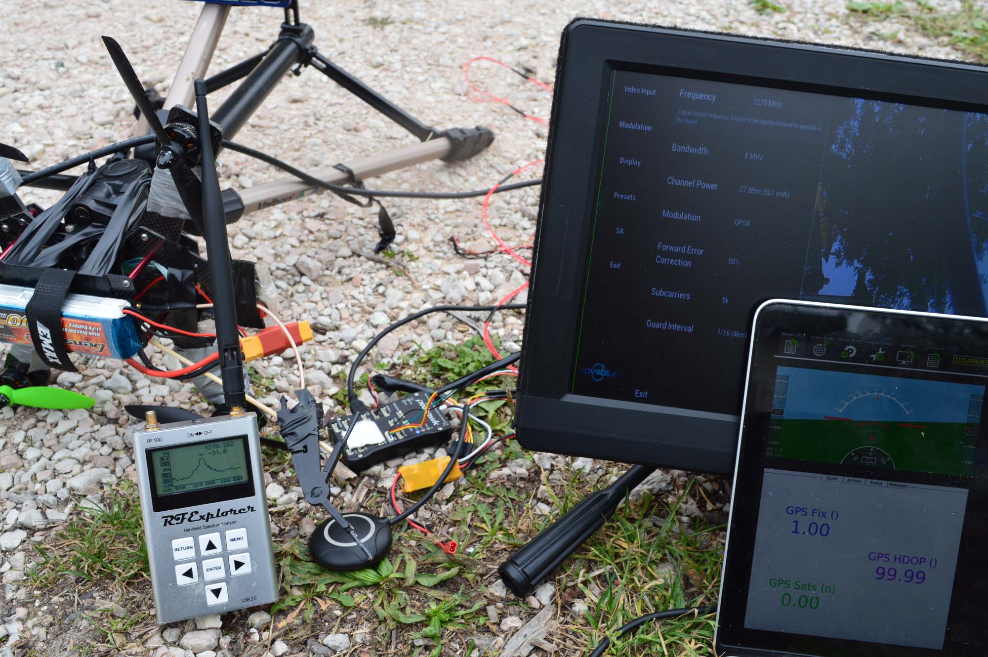
Still pretty bad, but much better. I then tried to go down in frequency in 5 MHz intervals until I got too bored. Nothing very interesting happened, as you can expect some frequencies are working better than others.
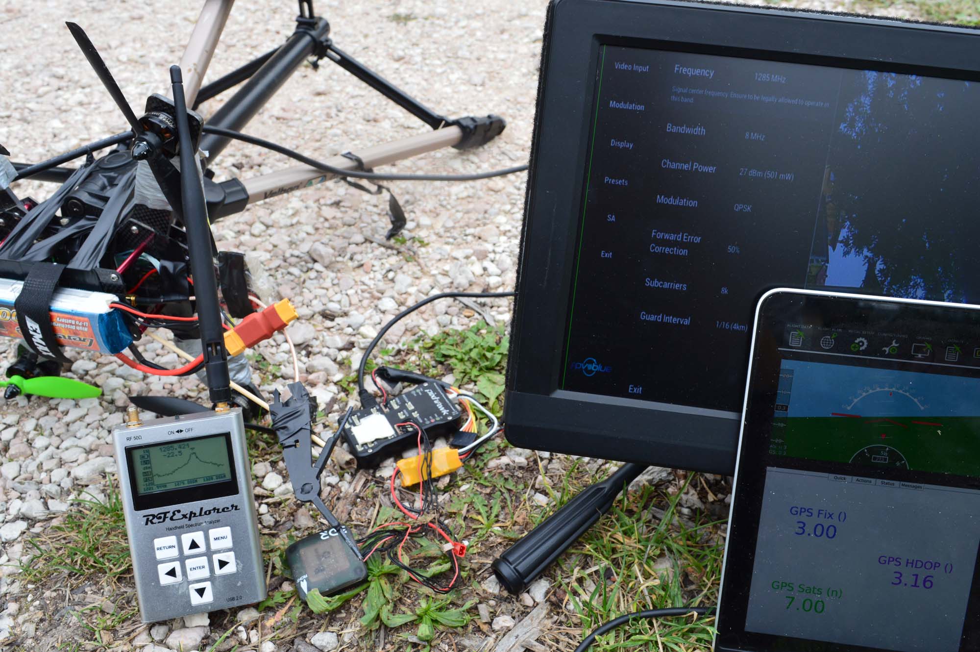
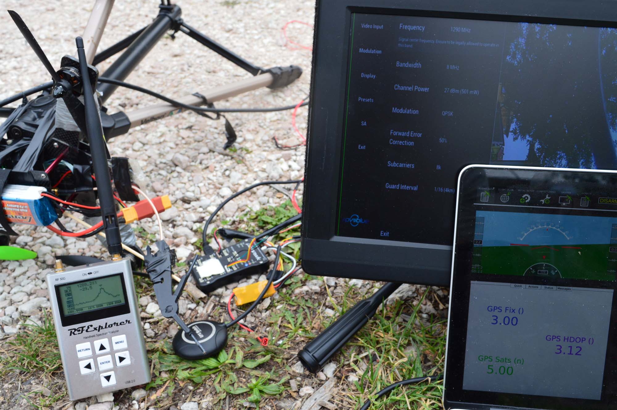
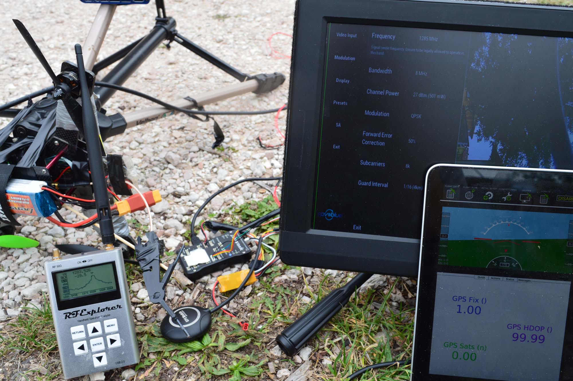
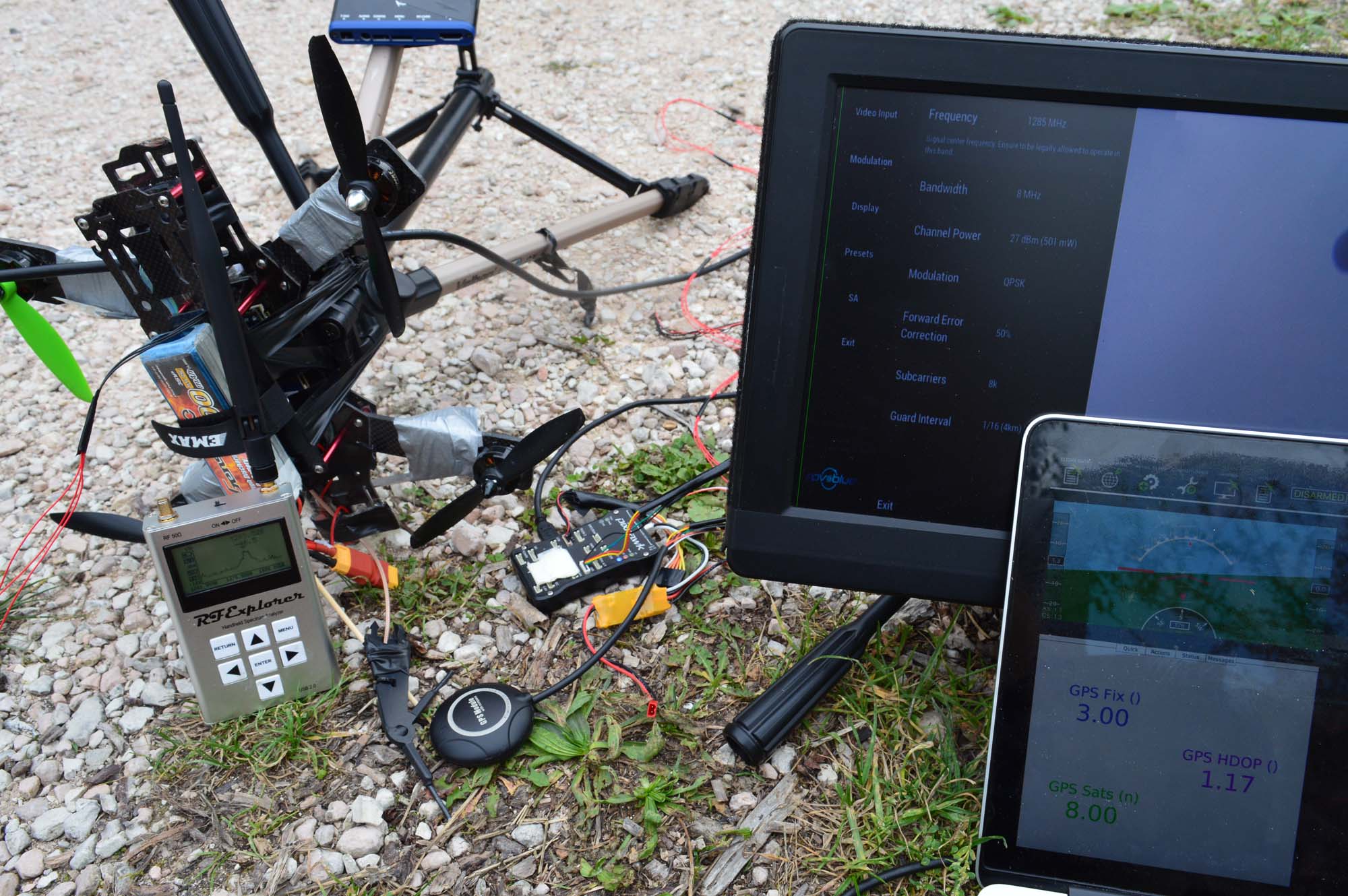
Most of the frequencies are killing the GPS receiver. Here is with the transmitter disconnected:
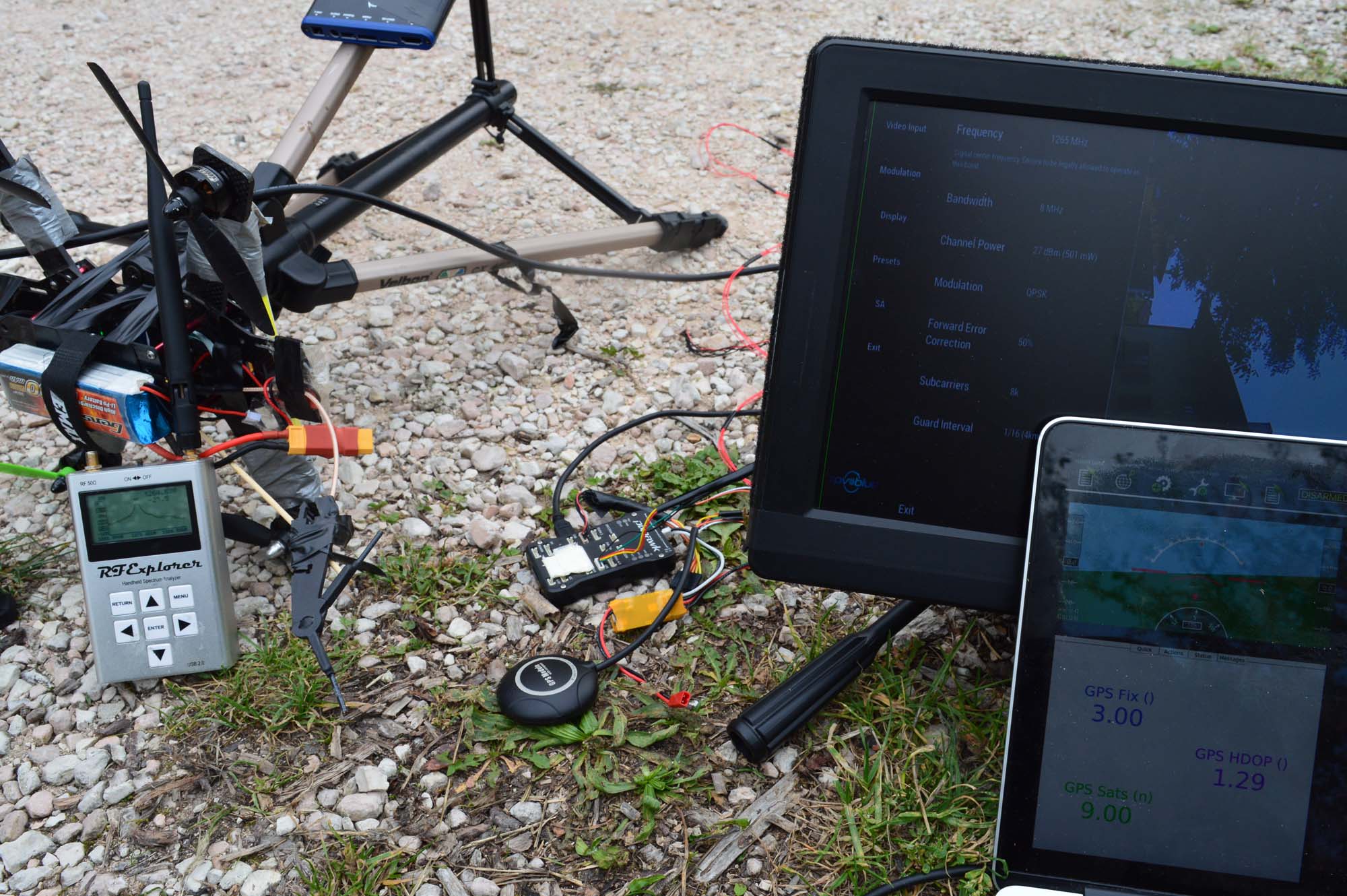
And here is with the transmitter not perfectly above the GPS receiver, as you can see performances are improving dramatically:
The finger is again to get very accurate distance measurements. By this time I’m getting tired. Let’s try to see what happens with the antenna on the same plane as the GPS unit, a few centimetres away.
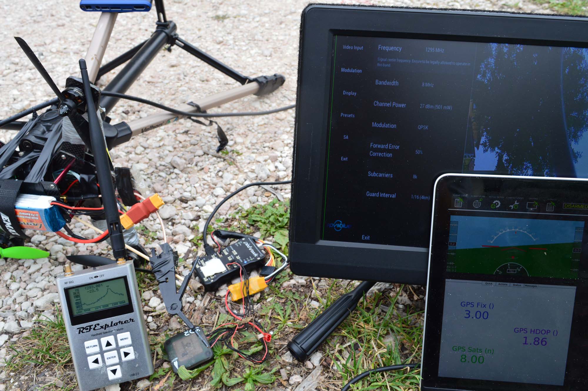
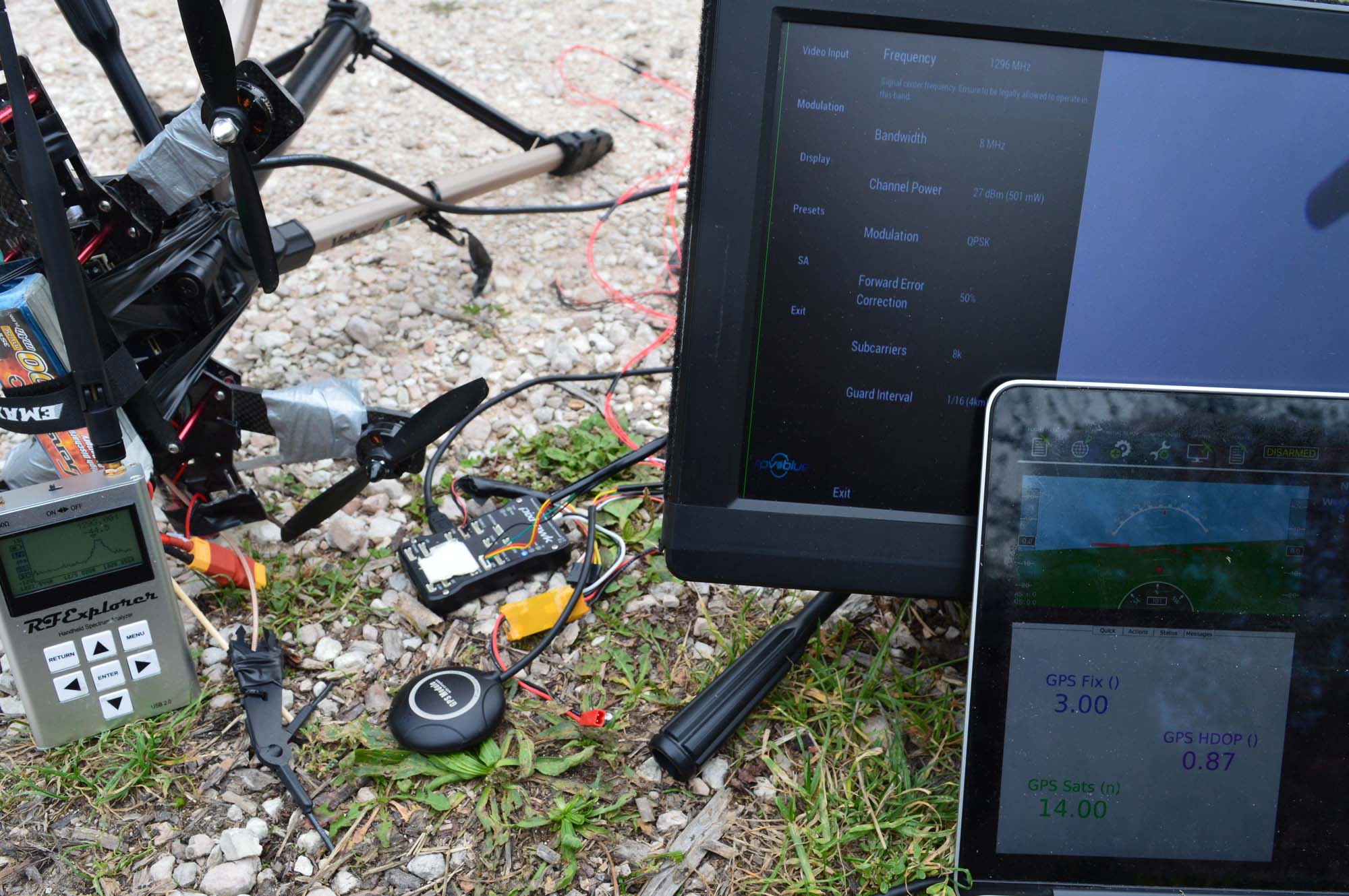
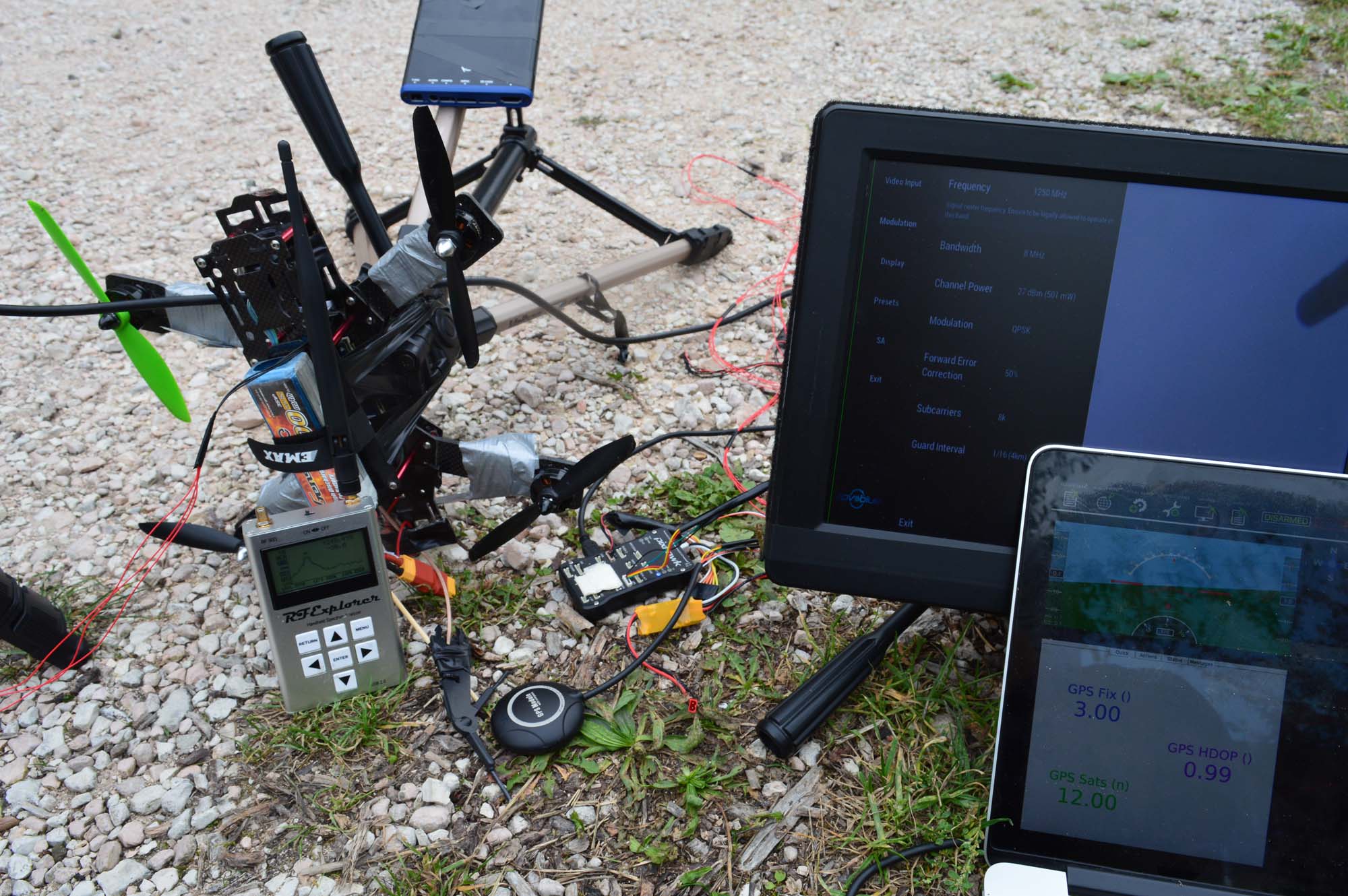
Perfect reception. We need to get closer.
A few sats lost. That’s more like it. Here comes the last batch of images, another frequency run at this distance.
And it’s with an antenna 0-cm away, 12 sats and a 0.99 HDOP that we conclude this blog post.
Takeaways
This transmitter works in the 1240-1300 MHz band. Some GPS frequencies are just below, others are just above it. It’s the first version of our transmitter and RF filtering isn’t as good as we would like it to be. Filtering ~250 MHz away is hard, not to say impossible.
In the meanwhile, here are our suggestions:
Fly with a recent GPS unit. The Ublox M8N was, in our opinion, performing great. If you have a Vector GPS V1, please upgrade to V2. Our V2 results were pretty good (and again, we couldn’t test V1).
Try mounting the transmitting antenna lower than the GPS receiver. The GPS receiver’s patch should be pointing at the sky with its RF aperture unobstructed. If you can’t mount the GPS higher, try to mount it at least on the same plane, don’t mount the video transmitting unit higher.
Test what your results are for the frequencies you want to use. Those new generation GPS receivers take just a few seconds to lock in a lot of satellites, there is no reason not to test them for the frequency you selected before your flight.
It might not be a good idea to use an old GPS unit mounted close to the transmitter/antenna.
Don’t fly if you are not happy with your HDOP. Send us an email instead.
That was a long post. Now let’s see if I can mange to finish this firmware on time.
After having introduced an automated latency measurement method in the last blog post, we used it to test several combinations of monitors and FPV systems, both digital and analog.
Transmission systems tested:
Analog: standard 5.8 GHz system with a CCTV camera (XK-3089).
Analog: standard 5.8 GHz system with a GoPro camera, running at 720p and 100fps.
Digital: Amimon Prosight, in both HP (High Performance) and HQ (High Quality) modes.
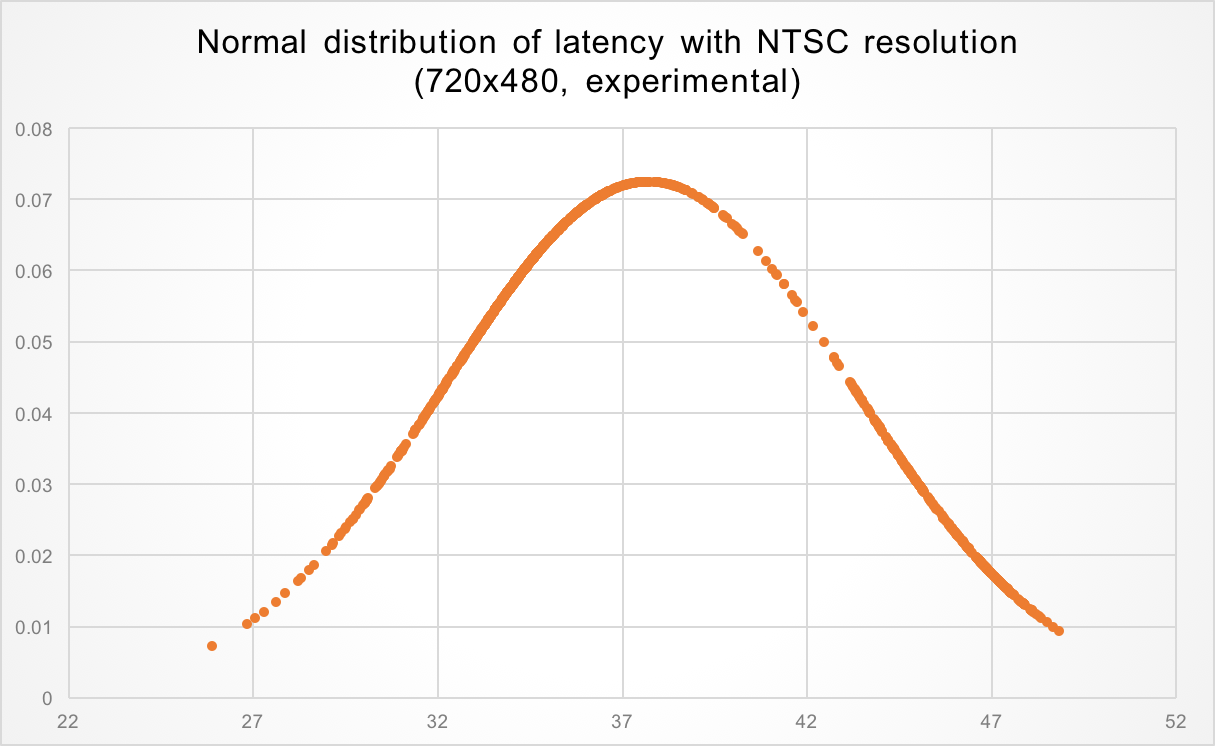
Digital: fpv.blue, using the HDMI input (GoPro, 720p@50fps) and custom camera (at 720p and 480p).
Digital: Wifibroadcast with default settings, running on a Raspberry Pi 1 on the transmitter and a Raspberry Pi 2 on the receiver.
Display devices tested:
Analog: a simple FPV monitor (RMRC-LCD-12).
Analog and Digital: Headplay HD googles.
Digital: a simple HD monitor (part numbers LQ121K1LG52, M.NT68676.2A).
Procedure
The previous blog post goes into the methodology with more detail, but we are using a photodiode, a Texas Instruments OPT101P, to measure video latency. The measurement starts from a random point in time by toggling a LED via an Arduino and checking how long the photodiode takes to detect a change in light (code here). This has several advantages over the standard stopwatch method, as already explained.
Data
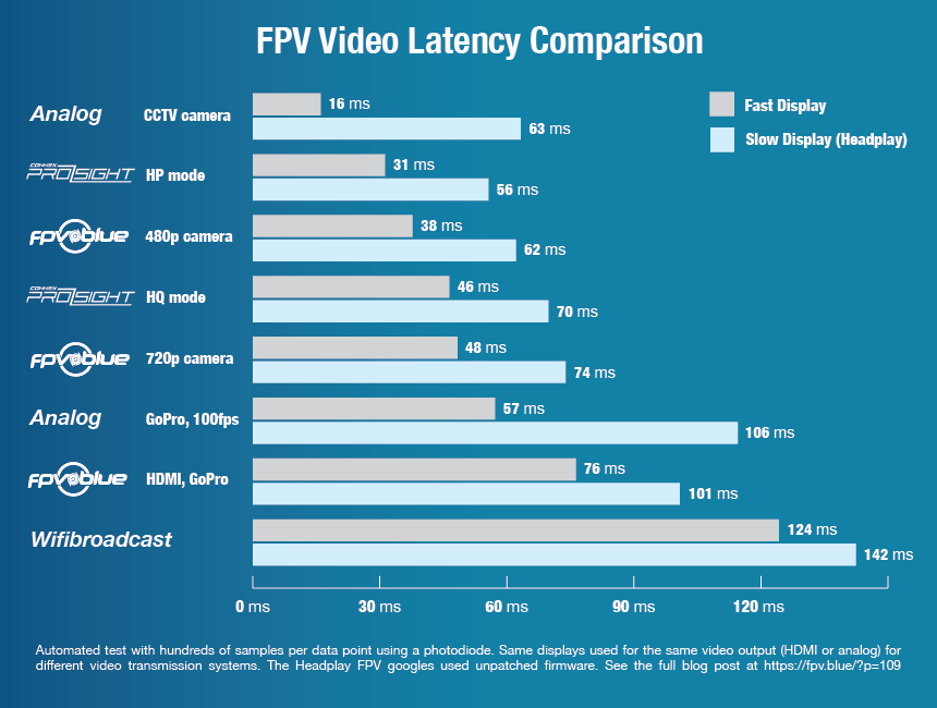
The raw results can be downloaded from here. The following is a graph visualising them that we invite you to take as a comparison point next time you are thinking about latency.
Comments
The display device matters. A lot. If you flown with an analog system and Headplay glasses you already experienced more latency than many digital FPV configurations.
Analog systems are still the only ones that can claim close to zero latency. Digital systems are, at best, two times slower.
Increasing GoPro framerate over 50 fps hoping to decrease analog output latency does not help. In fact, latency increased by a few milliseconds in our tests when going from 50 to 100 fps.
The analog video output of a GoPro at 50 or 100 fps is also slower than many digital FPV solutions.
HDMI display devices are not immune from display latency. The Headplay glasses introduced an average of 24 milliseconds latency when feed with a 720p stream and only 16 ms when feed with a 1280×800 stream. The additional 6 milliseconds are explained by the time the Headplay takes to resize the image from 720p to 1280×800, something that does not need to happen if the native resolution is correctly provided (well done, Wifibroadcast!).
A word of advice if you decide to replicate the test. Do it with battery powered devices only. Displays, oscilloscopes, etc., were all creating too much noise in the photodiode voltage sensor, making measurements tricky. If you need some help replicating those numbers don’t hesitate to send an email.
A couple of months ago, when we first announced the product specifications, we had a video latency figure of around 80 milliseconds. That number had a note attached to it: a promise to substantially lower it, to 50 milliseconds or less.
This kept us busy for much more than anticipated and required a hardware revision, but it finally happened. This post talks about how FPV latency is usually measured, what FPV latency actually is, how we are measuring this number (how would you measure sub-frame latencies?) and ends with some test results.
The wrong way of measuring FPV latency
The “industry standard” in measuring video latency is nothing short of terrible. It goes something like this: take a portable device, run some kind of stopwatch application on it, point the FPV camera to its screen, take a picture including both FPV screen and stopwatch, subtract the difference.
As you can see, there are several elements here that can influence (timing) resolution: the freeware stopwatch not being written for the application (simply simulating a live, running stopwatch, and not actually implementing one with live output), the digital camera frame exposure time if the two stopwatches are not horizontally aligned (rolling shutter), the portable device display refresh rate, the FPV video system framerate, etc. All together those errors can easily exceed the actual latency of an analog FPV system, where glass to glass latency is usually around 20 milliseconds, a number that is not possible to measure when using the stopwatch method.
A definition of latency
Before measuring it, we better define it. Sure, latency is the time it takes for something to propagate in a system, and glass to glass latency is the time it takes for something to go from the glass of a camera to the glass of a display. However, what is that something? If something is a random event, is it happening in all of the screen at the same time, or is restricted to a point in space? If it is happening in all of the camera’s lenses at the same time, do we consider latency the time it takes for the event to propagate in all of the receiving screen, or just a portion of it? The difference between the two might seem small, but it is actually huge.
Consider a 30 fps system, where every frame takes 33 milliseconds. Now consider the camera of that system. To put it simply, every single line of the vertical resolution (say, 720p) is read in sequence, one at the time. The first line is read and sent to the video processor. 16 milliseconds later the middle line (line 360) is read and sent to the processor. 33 milliseconds from start the same happens to the last line (line 720). What happens when an event occurs on the camera glasses at line 360 and the camera just finished reading it? That’s easy, it is going to take the camera the time of a full frame (33 milliseconds) to even notice something changed. That information will have to be sent to the processor and down the line up to the display, but even by supposing all that to be latency-free (it is not), it takes the time of a full frame, 33 milliseconds, to propagate a random event from a portion of the screen in a worst case scenario.
That is what happens to analog systems, where the interlaced 60 frames per second are converted to 30 progressive and are affected by this latency. There is no such a thing as zero latency. It’s just a marketing gimmick, sustained by the difficulty of actually measuring those numbers.
Measuring latency with sub-frame resolution
Or, measuring the propagation time of a random event from and to a small portion of the camera/display, because the other way is wrong (it only partially takes framerate into account).
A simple way of doing it is to use an Arduino, light up a LED and measure the time it takes for some kind of sensor to detect a difference in the display. The sensor needs to be fast, and the most oblivious choice for the job (a photoresistor) is too slow, with some manufacturers quoting as much as 100 milliseconds to detect a change in light. For this we need to use something more sophisticated, a photodiode, maybe with included amplifier. A Texas Instruments OPT101P was selected for the job. The diode is pretty fast in detecting light changes, try putting it below a LED table lamp and you will be able to see the LED switching on and off – something usually measured in microseconds. However measuring the time between two slightly different lights in a screen is going to take some tweaking and you might be forced to increase the feedback loop of the integrated op amp of something like 10M Ohms.
However, the end result is worth it: You will have a system capable of measuring FPV latency with milliseconds precision.
Blue line is the LED, yellow line is the photodiode. As can be seen from the picture in this case it takes around 45 milliseconds for the photodiode to detect the LED turning on, and around 55 milliseconds to detect it going off again.
fpv.blue’s latency
Now that we are done with the introductions let’s look at the actual numbers.
Over 1000 consecutive measurements, that you can download as a data dump from here, the average glass to glass latency for a random event in a restricted area of the screen is 49 milliseconds.
Minimum latency is 34 ms, maximum latency is 67 ms. Those numbers are compatible with what explained above: they depend on the current camera read position and display output position: for a a 60 fps system with 16 ms frame times this is latency average ± 16, or 33 and 65 ms.
So, there you have it, latency is now under 50 milliseconds, as promised.
Can it be lower?
Uhm. Not really. Maybe it could be possible to cut a total of 2-5 milliseconds with months of work, but such an optimisation is not planned at this stage.
However, that is for 720p. If you are ok with compromising on video quality and using speciality cameras that can output very high frame rates, then yes, it is possible to go even lower. In the following example the average latency is 38 milliseconds.
This was achieved with a frame rate of around 80 fps at both camera and display. Some cameras can go even faster and output VGA (not NTSC) at 120 fps, but this wasn’t tested.
However, for sub 30 milliseconds, that is probably the way to go.
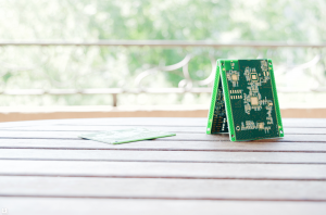
Our first prototyping PCBs arrived today! Three of those will compose a transmitter. They are currently 4.5 x 9 cm, but the size will be shrunk in the production model.